NCERT Books and the NCERT Syllabus for Class 12 form the foundation of board exam preparation and competitive exam readiness. Easy access to these links helps students follow the latest curriculum, understand topic-wise weightage, and prepare systematically for CBSE board examinations.
Search Colleges, Exams, Schools & more


Login
NCERT Solutions for Class 12 Physics Chapter 7 - Alternating Current
Have you ever questioned yourself why electrical appliances such as ceiling fans, refrigerators and washing machines can operate conveniently in our homes? This is achievable due to Alternating Current (AC) that changes its direction every now and then, compared to the Direct Current (DC), which flows in a single direction. Class 12 Physics Chapter 7 - Alternating Current describes the principles of working of the AC circuits, their properties, as well as their significance in the daily electrical systems.
This Story also Contains
- Class 12 Physics Chapter 7 - Alternating Current: Download PDF
- Class 12 Physics Chapter 7 - Alternating Current - Exercise Solutions
- Class 12 Physics Chapter 7 - Alternating Current: Additional Questions
- Class 12 Physics Chapter 7 - Alternating Current: Higher Order Thinking Skills (HOTS) Questions
- Class 12 Physics Chapter 7 - Alternating Current: Topics
- Class 12 Physics Chapter 7 - Alternating Current: Important Formulas
- Approach to solve questions of Class 12 Physics Chapter 7 - Alternating Current
- How Can NCERT Solutions for Class 12 Physics Chapter 7 Help in Exam Preparation?
- What Extra Should Students Study Beyond NCERT for JEE/NEET?
- NCERT Solutions for Class 12 Physics: Chapter-Wise
- NCERT Books and NCERT Syllabus
- NCERT Solutions Subject-wise
- NCERT Exemplar Class 12 Solutions

NCERT Solutions for Class 12 Physics Chapter 7 - Alternating Current are made by the highly qualified subject professionals based on the recent CBSE syllabus. These NCERT solutions introduce complex concepts like AC voltage and current, impedance, resonance, reactance, LC oscillations, transformers and power in AC circuits in a step-by-step, simple way, and therefore are simpler to comprehend and practice. NCERT Solutions for Class 12 Physics Chapter 7 - Alternating Current assist students in enhancing conceptual understanding, speed in solving numerical problems, and accuracy in problem-solving. These well-developed NCERT Solutions for Class 12 Physics Chapter 7 are very convenient in preparing for CBSE Class 12 board exams, competitive exams such as JEE and NEET.
Class 12 Physics Chapter 7 - Alternating Current: Download PDF
The Class 12 Physics Chapter 7 - Alternating Current question answers provide clear, step-by-step answers to all textbook questions, making it easier for students to master tough concepts. These Alternating Current class 12 question answers follow the latest NCERT syllabus and are available in a free downloadable PDF format for quick revision and exam preparation.
Class 12 Physics Chapter 7 - Alternating Current - Exercise Solutions
The Alternating Current NCERT Solutions (Exercise Questions) provide clear and comprehensible solutions to all textbook questions. These Alternating Current class 12 question answers also assist students to understand core ideas such as AC circuits, the flow of current, and RMS values, therefore, making the preparation of exams and solving problems more time-efficient.
Answer:
Given,
RMS voltage in the circuit $V_{rms}=220V$
Resistance in the circuit $R=100\Omega$
Now,
RMS current in the circuit:
$I_{rms}=\frac{V_{rms}}{R}=\frac{220}{100}=2.2A$
Hence, the RMS value of the current is 2.2A.
Answer:
Given,
Supplied RMS Voltage $V_{rms}=220V$
Supplied RMS Current $I_{rms}=2.2A$
The net power consumed over a full cycle:
$P=V_{rms}I_{rms}=220*2.2=484W$
Hence net power consumed is 484W.
Q7.2 (a) The peak voltage of an ac supply is $300 V$. What is the RMS voltage?
Answer:
Given
Peak Value of ac supply:
$V_{peak}=300V$
Now, as we know, in any sinusoidal function
RMS value = $\frac{peakvalue}{\sqrt{2}}$
Since our AC voltage supply is also sinusoidal
$V_{rms}=\frac{V_{peak}}{\sqrt{2}}=\frac{300}{\sqrt{2}}=212.13V$
Hence RMS value of the voltage is 212.13V.
Q7.2 (b) The RMS value of current in an ac circuit is $10\: A$. What is the peak current?
Answer:
Given,
RMS value of current $I_{rms}=10A$
Since Current is also sinusoidal (because only resistance is present in the circuit, not the capacitor and inductor)
$I_{rms}=\frac{I_{peak}}{\sqrt{2}}$
$I_{peak}=\sqrt{2}I_{rms}=\sqrt{2}*10=14.1A$
Hence, the peak value of current is 14.1A.
Answer:
Given
Supply Voltage $V=220V$
Supply Frequency $f=50Hz$
The inductance of the inductor connected $L=44mH=44*10^{-3}H$
Now
Inductive Reactance
$X_L=\omega L=2\pi fL=2\pi *50*44*10^{-3}$
RMS Value of the current :
$I_{rms}=\frac{V_{rms}}{X_L}= \frac{220}{2\pi *50*44*10^{-3}}=15.92A$
Hence, the RMS Value of the current is 15.92A.
Answer:
Given,
Supply Voltage $V = 110V$
Supply Frequency $f=60Hz$
The capacitance of the connected capacitor $C=60\mu F=60*10^{-6}F$
Now,
Capacitive Reactance
$X_C=\frac{1}{\omega C}=\frac{1}{2\pi fC}=\frac{1}{2\pi *60*60*10^{-6}}$
RMS Value of current
$I_{rms}=\frac{V_{rms}}{X_C}=V\omega C=V2\pi fC=110*2\pi *60*60*10^{-6}=2.49A$
Hence, the RMS Value of the current is 2.49A.
Answer:
As we know,
Power absorbed $P=VIcos\phi$
Where $\phi$ is the phase difference between voltage and current.
$\phi$ for the inductive circuit is -90 degree and $\phi$ for the capacitive circuit is +90 degree.
In both cases (inductive and capacitive), the power absorbed by the circuit is zero because in both cases the phase difference between current and voltage is 90 degrees.
This can be seen as the elements(Inductor and Capacitor) are not absorbing the power, but rather storing it. The capacitor is storing energy in electrostatic form, and the Inductor is storing the energy in magnetic form.
Answer:
Given
Capacitance $C=30\mu F=30*10^{-6}$
Inductance $L = 27mH = 27*10^{-3}H$
Now,
Angular Frequency
$\omega _r=\frac{1}{\sqrt{LC}}=\frac{1}{\sqrt{30*10^{-6}*27*10^{-3}}}=1.11*10^{3}rad/sec$
Hence Angular Frequency is $1.11*10^{3}rad/sec$
Answer:
Given,
Resistance $R=20\Omega$
Inductance $L=1.5H$
Capacitance $C=35\mu F=35*10^{-6}F$
Voltage supply $V = 200V$
At resonance, the supply frequency is equal to the natural frequency, and at the natural frequency, the total impedance of the circuit is equal to the resistance of the circuit
Inductive and capacitive reactance cancel each other. In other words,
$Z = \sqrt{\left ( \omega L-\frac{1}{\omega C} \right )^2+R^2}=\sqrt{0^2+R^2}=R=20\Omega$
As
$\omega L=\frac{1}{\omega C}$
Now,
Current in the circuit
$I=\frac{V}{Z}=\frac{200}{20}=10A$
Average Power transferred in the circuit :
$P=VI=200*10=2000W$
Hence average power transferred is 2000W.
Answer:
Given,
Variable frequency supply voltage $V$ = 230V
Inductance $L=5.0H$
Capacitance $C=80\mu F=80*10^{-6}F$
Resistance $R=40\Omega$
a) Resonance angular frequency in this circuit is given by :
$w_{resonance}=\frac{1}{\sqrt{LC}}=\frac{1}{\sqrt{5*80*10^{-6}}}=\frac{1000}{20}=50rad/sec$
Hence, this circuit will be in resonance when the supply frequency is 50 rad/sec.
Q7.8 (b) Figure shows a series LCR circuit connected to a variable frequency $230\: V$ source. $L=5.0H$ , $C=80\mu F$ , $R=40\Omega$. Obtain the impedance of the circuit and the amplitude of the current at the resonating frequency.

Answer:
Given,
Variable frequency supply voltage $V$ = 230V
Inductance $L=5.0H$
Capacitance $C=80\mu F=80*10^{-6}F$
Resistance $R=40\Omega$
Now,
The impedance of the circuit is
$Z=\sqrt{(wL-\frac{1}{wC})^2+R^2}$
At Resonance Condition
$wL=\frac{1}{wC}$
$Z=R=40\Omega$
Hence, the Impedance at resonance is 40 $\Omega$.
Now, at the resonance condition, impedance is minimum, which means the current is maximum, which will happen when we have a peak voltage, so
Current in the Resonance circuit is given by
$I_{resonance}=\frac{V_{peak}}{Z}=\frac{\sqrt{2}* 230}{40}=8.13A$
Hence amplitude of the current at resonance is 8.13A.
Q7.8 (c)Figure shows a series LCR circuit connected to a variable frequency $230\: V$ source.
$L=5.0H$ , $C=80\mu F$ , $R=40\Omega$ .

Answer:
Potential difference across any element = $I_{rms}*(impedance)$
$I_{rms}=\frac{I_{peak}}{\sqrt{2}}=\frac{8.13}{\sqrt{2}}=5.85A$
Now
The potential difference across the capacitor:
$V_{capacitor}=I_{rms}*\left (\frac{1}{w_{resonance}C} \right ) =5.85*\left ( \frac{1}{50*80*10^{-6}} \right )=1437.5V$
The potential difference across the inductor
$V_{inductor}=I_{rms}*(w_{resonance}L) =5.85* 50*5=1437.5V$
The potential difference across the Resistor
= 40 $I_{rms}$ = 230V
The potential difference across the LC combination
$V_{LC}=I_{rms}*\left ( wL-\frac{1}{wC} \right )=5.85*0=0$
Hence, at resonance, the potential difference across the LC combination is zero.
Also Read
Class 12 Physics Chapter 7 - Alternating Current: Additional Questions
The Additional Questions in Class 12 Physics Chapter 7 - Alternating Current provide extra practice beyond the textbook exercises. These questions help students strengthen their understanding of AC concepts, improve problem-solving skills, and prepare effectively for board exams and competitive tests like JEE and NEET.
What is the total energy stored initially? Is it conserved during $LC$ oscillations?
Answer :
Given,
The inductance of the inductor:
$L=20mH=20*10^{-3}H$
The capacitance of the capacitor :
$C=50\mu F=50*10^{-6}F$
The initial charge on the capacitor:
$Q=10mC=10*10^{-3}C$
Total energy present at the initial moment:
$E_{initial}=\frac{Q^2}{2C}=\frac{(10*10^{-3})^2}{2*50*10^{-6}}=1J$
Hence initial energy in the circuit is 1J. Since we don't have any power-consuming elements like resistance in the circuit, the energy will be conserved
What is the natural frequency of the circuit?
Answer:
Given,
The inductance of the inductor:
$L=20mH=20*10^{-3}H$
The capacitance of the capacitor :
$C=50\mu F=50*10^{-6}F$
The initial charge on the capacitor:
$Q=10mC=10*10^{-3}C$
The natural angular frequency of the circuit:
$w_{natural}=\frac{1}{\sqrt{LC}}=\frac{1}{\sqrt{(20*10^{-3}*50*10^{-6})}}=10^3rad/sec$
Hence, the natural angular frequency of the circuit is $10^3rad/sec$.
The natural frequency of the circuit:
$f_{natural}=\frac{w_{natural}}{2\pi}=\frac{10^3}{2\pi}=159Hz$
Hence, the natural frequency of the circuit is 159Hz.
Q1. (c-i) An $LC$ circuit contains a $20mH$ inductor and a $50\mu F$ capacitor with an initial charge of $10mC$ . The resistance of the circuit is negligible. Let the instant the circuit is closed be $t=0$ . At what time is the energy stored completely electrical (i.e., stored in the capacitor)?
Answer:
At any instant, the charge on the capacitor is:
$Q=Q_0cos(w_{natural}t)=Q_0cos(2\pi f_{natural}t)=Q_0cos\left ( \frac{2\pi t}{T} \right )$
Where time period :
$T=\frac{1}{f_{natural}}=\frac{1}{159}=6.28ms$
Now, when the total energy is purely electrical, we can say that
$Q=Q_0$
$Q_0=Q_0cos(\frac{2\pi}{T})$
$cos(\frac{2\pi t}{T})=1$
This is possible when
$t=0,\frac{T}{2},T,\frac{3T}{2}....$
Hence, Total energy will be purely electrical(stored in a capacitor) at
$t=0,\frac{T}{2},T,\frac{3T}{2}....$ .
Q1.(c-ii) An $LC$ circuit contains a $20mH$ inductor and a $50\mu F$ capacitor with an initial charge of $10mC$ . The resistance of the circuit is negligible. Let the instant the circuit is closed be $t=0$ . At what time is the energy stored completely magnetic (i.e., stored in the inductor)?
Answer:
The stored energy will be purely magnetic when the pure electrical stored is zero. i.e. when the charge on the capacitor is zero, all energy will be stored in the inductor.
So, the time for which the charge on the capacitor is zero is
$t=\frac{T}{4},\frac{3T}{4},\frac{5T}{4}..$
Hence, at these times, the total energy will be purely magnetic.
Q1. (d) An $LC$ circuit contains a $20mH$ inductor and a $50\mu F$ capacitor with an initial charge of $10mC$ . The resistance of the circuit is negligible. Let the instant the circuit is closed be $t=0$ . At what times is the total energy shared equally between the inductor and the capacitor?
Answer:
The energy will be shared equally when the energy in the capacitor is half of the maximum energy it can store. i.e.
$\frac{Q^2}{2C}=\frac{1}{2}\frac{Q_0^2}{2C}$
From here, we got
$Q=\frac{Q_0}{\sqrt{2}}$
So now, we know the charge on the capacitor, we can calculate the time for which
$\frac{Q_0}{\sqrt{2}}=Q_0cos\left ( \frac{2\pi t}{T} \right )$
$\frac{1}{\sqrt{2}}=cos\left ( \frac{2\pi t}{T} \right )$
From here,
$t=\frac{T}{8},\frac{3T}{8},\frac{5T}{8}..$
Hence, for these times, the total energy will be shared equally between the capacitor and the inductor.
Q1. (e) An $LC$ circuit contains a $20mH$ inductor and a $50\mu F$ capacitor with an initial charge of $10mC$. The resistance of the circuit is negligible. Let the instant the circuit is closed be $t=0$. If a resistor is inserted in the circuit, how much energy is eventually dissipated as heat?
Answer:
If the resistance is added to the circuit, the whole energy will eventually dissipate as heat. Energy will keep moving between the capacitor and inductor with a reduction in magnitude in each cycle, and eventually, all energy will be dissipated.
Answer:
Given,
The inductance of the coil $L=0.50H$
The resistance of the coil $R=100\Omega$
Supply voltage $V=240V$
Supply voltage frequency $f=50Hz$
Now, as we know peak voltage = $\sqrt2$ (RMS Voltage)
Peak voltage
$V_{peak}=\sqrt2*240=339.4V$
The impedance of the circuit :
$Z=\sqrt{R^2+(wL)^2}=\sqrt{100^2+(2\pi (.5) *50)^2}$
Now peak current in the circuit :
$I_{peak}=\frac{V_{peak}}{Z}=\frac{339}{\sqrt{100^2+(2\pi (.5) *50)^2}}=1.82A$
Hence peak current is 1.82A in the circuit.
Answer:
Let the voltage in the circuit be
$V = V_0coswt$ and
Current in the circuit is
$I = I_0cos(wt-\phi )$
Where $\phi$ is the phase difference between voltage and current.
V is maximum at
t = 0
$I$ is maximum at
$t=\frac{w}{\phi }$
Hence, the time lag between the voltage maximum and the current maximum is $\frac{w}{\phi }$.
For phase difference $\phi$ we have
$tan\phi =\frac{wL}{R}=\frac{2\pi *50*0.5}{100}=1.57$
$\phi =57.5^0$
$t=\frac{\phi}{w}=\frac{57.5*\pi}{180*2\pi *50}=3.2ms$
Hence time lag between the maximum voltage and the maximum current is $3.2ms$
Answer:
Given,
The inductance of the coil $L=50H$
The resistance of the coil $R=100\Omega$
Supply voltage $V=240V$
Supply voltage frequency $f=10kHz$
a)
Now, as we know peak voltage = $\sqrt2$ (RMS Voltage)
Peak voltage $V_{peak}=\sqrt2*240=339.4V$
Now,
The impedance of the circuit :
$Z=\sqrt{R^2+(wL)^2}=\sqrt{100^2+(2\pi 10*10^3 *50)^2}$
Now peak current in the circuit :
$I_{peak}=\frac{V_{peak}}{Z}=\frac{339}{\sqrt{100^2+(2\pi 10*10^3 *50)^2}}=1.1*10^{-2}A$
Hence, peak current is $1.1*10^{-2}A$ in the circuit.
The current in the circuit is very small, which is one of the indications of the inductor working as a nearly open circuit in the case of high frequency.
b)
For phase difference $\phi$ we have
$tan\phi =\frac{wL}{R}=\frac{2\pi *10*10^3*0.5}{100}=100\pi$
$\phi =89.82^0$
Now
$t=\frac{\phi}{w}=\frac{89.82*\pi}{180*2\pi *10^3}=25\mu s$
Hence time lag between the maximum voltage and the maximum current is $25\mu s$.
In the DC circuit, after attaining the steady state, the inductor behaves line short circuit as $w$ is zero.
Answer:
Given,
The capacitance of the capacitor $C=100\mu F$
The resistance of the circuit $R=40\Omega$
Voltage supply $V = 100V$
Frequency of voltage supply $f=60Hz$
The maximum current in the circuit
$I_{max}=\frac{V_{max}}{Z}=\frac{\sqrt{2}V}{\sqrt{R^2+\left ( \frac{1}{wC} \right )^2}}=\frac{\sqrt{2}*110}{\sqrt{40^2+\left ( \frac{1}{2\pi *60*100*10^{-6}} \right )^2}}=3.24A$
Hence maximum current in the circuit is 3.24A.
Answer:
In the case of a capacitor, we have
$tan\phi=\frac{\frac{1}{wC}}{R}=\frac{1}{wCR}$
So,
$tan\phi=\frac{1}{wCR}=\frac{1}{2\pi 60 *100*10^{-6}*40}=0.6635$
$\phi=33.56^0$
So the time lag between the max voltage and the max current is :
$t=\frac{\phi }{w}=\frac{33.56\pi}{180*2\pi*60}=1.55ms$
Answer:
Given,
The capacitance of the capacitor $C=100\mu F$
The resistance of the circuit $R=40\Omega$
Voltage supply $V = 100V$
Frequency of voltage supply $f=12kHz$
The maximum current in the circuit
$I_{max}=\frac{V_{max}}{Z}=\frac{\sqrt{2}V}{\sqrt{R^2+\left ( \frac{1}{wC} \right )^2}}=\frac{\sqrt{2}*110}{\sqrt{40^2+\left ( \frac{1}{2\pi *12*10^3*100*10^{-6}} \right )^2}}=3.9A$
Hence maximum current in the circuit is 3.9A.
b)
In the case of a capacitor, we have
$tan\phi=\frac{\frac{1}{wC}}{R}=\frac{1}{wCR}$
So,
$tan\phi=\frac{1}{wCR}=\frac{1}{2\pi 10*10^3 *100*10^{-6}*40}=\frac{1}{96\pi}$
$\phi=0.2^0$
So the time lag between max voltage and max current is :
$t=\frac{\phi }{w}=\frac{0.2\pi}{180*2\pi*60}=0.04\mu s$
At high frequencies, $\phi$ tends to zero. which indicates capacitor acts as a conductor at high frequencies.
In the DC circuit, after a steady state is achieved, the Capacitor acts like an open circuit.
Answer:
As we know, in the case of a parallel RLC circuit:
$\frac{1}{Z}=\sqrt{\frac{1}{R^2}+(wC-\frac{1}{wL})^2}$
$I=\frac{V}{Z}={V}{\sqrt{\frac{1}{R^2}+\left (wC- \frac{1}{wL} \right )^2}}$
The current will be minimal when
$wC=\frac{1}{wL}$
This is also the condition of natural frequency. Hence, the total current is minimum when the source frequency is equal to the natural frequency.
RMS value of current in R
$I_{rms}=\frac{V_{rms}}{R}=\frac{230}{40}=5.75A$
RMS value in Inductor
$I_{inductor}=\frac{V_{rms}}{wL}=\frac{230}{5*50}=0.92A$
RMS value in a capacitor
$I_{capacitor}=\frac{V_{rms}}{1/wL}={230*50*80*10^{-6}}=0.92A$
Capacitor current and inductor current will cancel each other out, so the current flowing in the circuit is 5.75A.
Answer:
The inductance of the inductor $L=80mH=80*10^{-3}H$
The capacitance of the capacitor $C=60\mu F$
Voltage supply $V = 230V$
Frequency of voltage supply $f=50Hz$.
Here, we have
$V=V_{max}sinwt=V_{max}sin2\pi ft$
Impedance
$Z=\sqrt{R^2+\left ( wL-\frac{1}{wC} \right )^2}$
$Z=\sqrt{0^2+\left ( 2\pi*50*80*10^{-3}-\frac{1}{2\pi 50*60*10^{-6}} \right )^2}=8\pi-\frac{1000}{6\pi }$
Now,
Current in the circuit will be
$I=\frac{V}{Z}=\frac{V_{max}sinwt}{Z\angle \phi }=I_{max}sin(wt-\phi )$
where,
$I_{max}=\frac{V_{max}}{Z}=\frac{\sqrt{2}*230}{8\pi-\frac{1000}{6\pi}}=-11.63A$
The negative sign is just a matter of the direction of the current. So,
$I=11.63sin(wt-\phi )$
here
$tan\phi=\frac{wL-\frac{1}{wC}}{R}$
But, since the value of R is zero(since our circuit has only L and C)
$\phi=90^0$
Hence
$I=11.63sin(wt-\frac{\pi}{2} )$
Now,
RMS value of this current:
$I_{rms}=\frac{I_{max}}{\sqrt{2}}=\frac{11.63}{\sqrt{2}}=8.22A$ .
Answer:
As we know,
RMS potential drop across an element with impedance Z:
$V_{element}=I_{rms}Z_{element}$
SO,
RMS potential difference across the inductor:
$V_{inductor}=I_{rms}*wL=8.22*2\pi *60*80*10^{-3}=206.61V$
RMS potential drop across the capacitor
$V_{capacitor}=I_{rms}*\frac{1}{wC}=8.22*\frac{1}{2\pi*60*60*10^{-6}}=436.3V$
Q7. (c) A circuit containing a $80mH$ inductor and a $60\mu F$ capacitor in series is connected to a $230\: V$ , $50\: Hz$ supply. The resistance of the circuit is negligible. What is the average power transferred to the inductor?
Answer:
Since
$I=I_{max}sin(wt-\phi )$
Current flowing in the circuit is sinusoidal, and hence average power will be zero as the average of the sine function is zero. In other words, the inductor will store energy in the positive half cycle of the sine (0 degrees to 180 degrees) and will release that energy in the negative half cycle(180 degrees to 360 degrees), and hence average power is zero.
Answer:
As we know,
Average power $P=VIcos\theta$ where $\theta$ is the phase difference between voltage and current.
Since in the circuit, the phase difference $\theta$ is $\pi/2$, the average power is zero.
Answer:
Since the phase difference between voltage and current is 90 degrees, the total power absorbed by the circuit is zero. This is an ideal circuit; we can not have any circuit in practice that consumes no power, that is because practically resistance of any circuit is never zero. Here, only the inductor and the capacitor are present, and neither of them consumes energy; they just store it and transfer it as they are doing in this case.
Answer:
The inductance of the inductor $L=80mH=80*10^{-3}H$
The capacitance of the capacitor $C=60\mu F$
The resistance of a $15\Omega$ resistor
Voltage supply $V = 230V$
Frequency of voltage supply $f=50Hz$
As we know,
Impedance
$Z=\sqrt{R^2+\left ( wL-\frac{1}{wC} \right )^2}$
$Z=\sqrt{15^2+\left ( 2\pi*50*80*10^{-3}-\frac{1}{2\pi 50*60*10^{-6}} \right )^2}=31.728$
Current flowing in the circuit :
$I=\frac{V}{Z}=\frac{230}{31.72}=7.25A$
Now,
Average power transferred to the resistor:
$P_{resistor}=I^2R=(7.25)^2*15=788.44W$
Average power transferred to the inductor = 0
Average power transferred to the capacitor = 0:
Total power absorbed by circuit :
$P_{resistor}+p_{inductor}+P_{capacitor}=788.44+0+0=788.44W$
Hence circuit absorbs 788.44W.
What is the source frequency for which the current amplitude is maximum? Obtain this maximum value.
Answer:
The inductance of the inductor $L=0.12H$
The capacitance of the capacitor $ C=480nF$
The resistance of the resistor $R=23\Omega$
Voltage supply $V = 230V$
Frequency of voltage supply $f=50Hz$
As we know,
The current amplitude is maximum at the natural frequency of oscillation, which is
$w_{natural}=\sqrt\frac{1}{LC}=\frac{1}{\sqrt{0.12*480*10^{-9}})}=4166.67rad/sec$
Also, at this frequency,
$Z=R=23$
So,
The maximum current in the circuit :
$I_{max}=\frac{V_{max}}{Z}=\frac{V_{max}}{R}=\frac{\sqrt{2*}230}{23}=14.14A$
Hence maximum current is 14.14A.
Answer:
Since the resistor is the only element in the circuit which consumes power, the maximum absorbed power by the circuit will be maximum when the power absorbed by the resistor is maximum. The power absorbed by the resistor will be maximum when the current is maximum, which is the natural frequency case.
Hence, when the source frequency is equal to the natural frequency, the power absorbed will be maximum.
Hence frequency
$f=\frac{w_r}{2\pi}=\frac{4166.67}{2\pi}=663.48Hz$
Maximum Power Absorbed
$P=I^2R=(14.14)^2*23=2299.3W$ .
Answer:
The value of the maximum angular frequency is calculated in the first part of the question, and its magnitude is 4166.67
Q-factor of any circuit is given by
$Q=\frac{w_rL}{R}=\frac{4166.67*0.12}{23}=21.74$
Hence Q-factor for the circuit is 21.74.
Answer:
As
Power $P=I^2R$
Power $P$ will be half when the current $I$ is $1/\sqrt{2}$ times the maximum current.
As,
$I =I_{max}Sin(wt-\phi)$
At half powerpoint :
$\frac{i_{max}}{\sqrt{2}} =I_{max}Sin(wt-\phi)$
$\frac{1}{\sqrt{2}} =Sin(wt-\phi)$
$wt=\phi+\frac{\pi}{4}$
here,
$\phi=tan^{-1}(\frac{wL-\frac{1}{wC}}{R})$
On putting values, we get two values of $w$ for which
$wt=\phi+\frac{\pi}{4}$
And they are:
$w_1=678.75Hz$
$w_2=648.22Hz$
Also,
The current amplitude at these frequencies
$I_{halfpowerpoint}=\frac{I_{max}}{\sqrt{2}}=\frac{14.14}{1.414}=10A$
Answer:
The inductance of the inductor $L=0.3H$
The capacitance of the capacitor $C=27\mu F$
The resistance of the resistor $R=7.4\Omega$
Now,
Resonant frequency
$w_r=\frac{1}{\sqrt{LC}}=\frac{1}{\sqrt{0.3*27*10^{-6}}}=111.11rad/sec$
Q-Factor of the circuit
$Q=\frac{w_rL}{R}=\frac{111.11*0.3}{7.4}=45.0446$
Now, to improve the sharpness of resonance by reducing its full width at half maximum by a factor of 2 without changing $w_r$,
We have to change the resistance of the resistor to half of its value, that is
$R_{new}=\frac{R}{2}=\frac{7.4}{2}=3.7\Omega$
Answer:
Yes, at any instant, the applied voltage will be distributed among all elements and the sum of the instantaneous voltage of all elements will be equal to the applied voltage. But this is not the case in RMS because all elements vary differently, and they may not be in the same phase.
Q11.(b) Answer the following questions: A capacitor is used in the primary circuit of an induction coil.
Answer:
Yes, we use capacitors in the primary circuit of an induction coil to avoid sparking. When the circuit breaks, a large emf is induced, and the capacitor gets charged from this, avoiding the case of sparking and short circuit.
Q11. (c) Answer the following questions: An applied voltage signal consists of a superposition of a $dc$ voltage and an ac voltage of high frequency. The circuit consists of an inductor and a capacitor in series. Show that the DC signal will appear across $C$ and the ac signal across $L$.
Answer:
For a high frequency, the inductive reactance and capacitive reactance:
$X_L=wL=Large \:value\: And \:X_C = \frac{1}{wC}=Very\:small$
Hence, the capacitor does not offer resistance to a higher frequency, so the ac voltage appears across L.
Similarly
For DC, the inductive reactance and capacitive reactance:
$X_L=wL=Very\:small\: And \:X_C = \frac{1}{wC}=Large \:value$
Hence DC signal appears across the Capacitor only.
Q11.(d) Answer the following questions: A choke coil in series with a lamp is connected to a DC line. The lamp is seen to shine brightly. Insertion of an iron core in the choke causes no change in the lamp’s brightness. Predict the corresponding observations if the connection is to an AC line.
Answer:
For a steady state DC, the increase in inductance value by inserting an iron core in the choke has no effect on the brightness of the connected lamp, whereas, for AC, when the iron core is inserted, the light of the lamp will shine less brightly because of an increase in inductive impedance.
Q11. (e) Answer the following questions: Why is a choke coil needed in the use of fluorescent tubes with AC mains? Why can we not use an ordinary resistor instead of the choke coil?
Answer:
We need a choke coil for the use of fluorescent tubes with AC mains to reduce the voltage across the tube without wasting much power. If we use a simple resistor for this purpose, there will be more power loss; hence, we do not prefer it.
Answer:
Given,
Input voltage:
$V_{input}=2300V$
Number of turns in the primary coil
$N_{primary}= 4000$
Output voltage:
$V_{output}=230V$
Now,
Let the number of turns in the secondary be
$N=N_{secondary}$
Now, as we know, in a transformer,
$\frac{V_{primary}}{V_{secondary}}=\frac{N_{primary}}{N_{secondary}}$
${N_{secondary}} =\frac{V_{secondary}}{V_{primary}}*N_{primary}=\frac{230}{2300}*4000=400$
Hence, the number of turns in the secondary winding is 400.
Answer:
Given,
Height of the water pressure head
$h=300m$
The volume of the water flow per second
$V=100m^3s^{-1}$
Turbine generator efficiency
$\eta =0.6$
Mass of water flowing per second
$M=100*10^3=10^5kg$
The potential energy stored in the fall for 1 second
$P=Mgh=10^5*9.8*300=294*10^6J$
Hence input power
$P_{input}=294*10^6J/s$
Now, as we know,
$\eta =\frac{P_{output}}{P_{input}}$
$P_{output}=\eta *P_{input}=0.6*294*10^6=176.4*10^6W$
Hence output power is 176.4 MW.
Answer:
Power required
$P=800kW=800*10^3W$
The total resistance of the two-wire line
$R=2*15*0.5=15\Omega$
Input Voltage
$V_{input}=4000V$
Output Voltage:
$V_{output}=220V$
RMS Current in the wireline
$I=\frac{P}{V_{input}}=\frac{800*10^3}{4000}=200A$
Now,
Power loss in the line
$P_{loss}=I^2R=200^2*15=600*10^3=600kW$
Hence, the power loss in the line is 600kW.
Q14. (b) A small town with a demand of $800 kW$ of electric power at $220V$ is situated $15km$ away from an electric plant generating power at $440V$. The resistance of the two-wire line carrying power is $0.5\Omega$ per km. The town gets power from the line through a $4000-220V$ step-down transformer at a sub-station in the town. How much power must the plant supply, assuming there is negligible power loss due to leakage?
Answer:
Power required
$P=800kW=800*10^3W$
The total resistance of the two-wire line
$R=2*15*0.5=15\Omega$
Input voltage
$V_{input}=4000V$
Output voltage:
$V_{output}=220V$
RMS current in the wireline
$I=\frac{P}{V_{input}}=\frac{800*10^3}{4000}=200A$
Now,
Total power delivered by plant = line power loss + required electric power = 800 + 600 = 1400kW.
Answer:
Power required
$P=800kW=800*10^3W$
The total resistance of the two-wire line
$R=2*15*0.5=15\Omega$
Input Voltage
$V_{input}=4000V$
Output Voltage:
$V_{output}=220V$
RMS Current in the wireline
$I=\frac{P}{V_{input}}=\frac{800*10^3}{4000}=200A$
Now,
Voltage drop in the power line = $IR=200*15=3000V$
Total voltage transmitted from the plant = 3000+4000=7000
As power is generated at 440V, the rating of the power plant is 440V-7000V.
Answer:
Power required
$P=800kW=800*10^3W$
The total resistance of the two-wire line
$R=2*15*0.5=15\Omega$
Input Voltage
$V_{input}=40000V$
Output Voltage:
$V_{output}=220V$
RMS current in the wireline
$I=\frac{P}{V_{input}}=\frac{800*10^3}{40000}=20A$
Now,
a) power loss in the line
$P_{loss}=I^2R=20^2*15=6kW$
b)
Power supplied by plant = 800 kW + 6 kW = 806 kW.
c)
Voltage drop in the power line = $IR=20*15=300V$
Total voltage transmitted from the plant = 300+40000=40300
As power is generated at 440V, the rating of the power plant is 440V-40300V.
We prefer high voltage transmission because the power loss is a lot less than low voltage transmission.
Confused between CGPA and Percentage?
Get your results instantly with our calculator!
💡 Conversion Formula used is: Percentage = CGPA × 9.5
Class 12 Physics Chapter 7 - Alternating Current: Higher Order Thinking Skills (HOTS) Questions
The Higher Order Thinking Skills (HOTS) Questions on Class 12 Physics Chapter 7 - Alternating Current are an opportunity presented to students to use their understanding of AC concepts in complex and real-life situations. These questions sharpen analytical skills, problem-solving and make the students ready to appear in higher tests such as JEE and NEET.
Q1: The power factor of R-L circuit is $\frac{1}{\sqrt{3}}$ If the inductive reactance is $2 \Omega$. The value of resistance is
Answer:
Power factor -
$
\begin{aligned}
& \cos \phi=\frac{R}{Z} \\
& R \rightarrow \text { resistance } \\
& Z \rightarrow \text { impedance }
\end{aligned}
$
And for the RL circuit
$
Z=\sqrt{R^2+\left(X_L\right)^2}
$
where $X_L=$ inductive reactance
So
Power factor $=\cos \phi=\frac{R}{Z}$
$
\Rightarrow \frac{1}{\sqrt{3}}=\frac{R}{\sqrt{R^2+2^2}}
$
On solving, we get
$
R=\sqrt{2} \Omega
$
Q2:

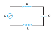
In the above circuit, $\mathrm{C}=\frac{\sqrt{3}}{2} \mu F, R_2=20 \Omega, L=\frac{\sqrt{3}}{10} H$ and $R_1=10 \Omega$. Current in $\mathrm{LR}_1$ path is $\mathrm{I}_1$ and in C-R2 path it is $\mathrm{I}_2$. The voltage of $\mathrm{A}. \mathrm{C}$ source is given by, $V=200 \sqrt{2} \sin (100 t)$ volts. The phase difference between $\mathrm{I}_1$ and $\mathrm{I}_2$ is : (in degrees)
Answer:
Phase difference -
$
\begin{aligned}
& \tan \phi=\frac{X_L}{R}=\tan ^{-1}\left(\frac{X_L}{R}\right) \\
& \phi=\tan ^{-1}\left(\frac{\omega L}{R}\right)
\end{aligned}
$
wherein
$
\mathrm{X}_{\mathrm{L}}=\text { inductive reactance }
$
R = resistance
Phase difference -
$
\begin{aligned}
& \tan \phi=\frac{X_c}{R} \\
& \phi=\tan ^{-1}\left(\frac{X_c}{R}\right)=\tan ^{-1}\left(\frac{1}{\omega c R}\right)
\end{aligned}
$
For current $\mathrm{I}_1$
$
\phi_1=\tan ^{-1} \frac{\omega L}{R_1}=\tan ^{-1}\left(\frac{100 \frac{\sqrt{3}}{10}}{10}\right)=60^{\circ} \text { (lagging) }
$
For $\mathrm{I}_2$ current
$
\begin{aligned}
& \phi_2=\tan ^{-1}\left(\frac{1}{\omega C R_2}\right)=\tan ^{-1}\left(\frac{10^6}{100 \times \frac{\sqrt{3}}{2} \times 20}\right) \approx 90^{\circ} \quad \text { (leading) } \\
& \text { Phase difference }=90+60=150^{\circ}
\end{aligned}
$
Q3: An inductance of $\left(\frac{200}{\pi}\right) \mathrm{mH}$ is connected with an AC source $220 \mathrm{~V}, 50 \mathrm{~Hz}$. The inductive susceptance of the circuit is:
Answer:
As we learn
Inductive susceptance
$
S_L=\frac{1}{X_L}=\frac{1}{2 \pi \nu L}
$
$\mathrm{X}_{\mathrm{L}}$ (inductive reactance)
$
X_L=2 \pi f L=2 \pi \times 50\left[\frac{200}{\pi} \times 10^{-3}\right]=20 \Omega
$
Inductive susceptance $=\frac{1}{X_L}=\frac{1}{20}=0.05$
Q4: Figure shows a series LCR circuit connected to a variable frequency 230 V source. $\mathrm{L}=5.0 \mathrm{H}$, $\mathrm{C}=80 \mu \mathrm{~F}, \mathrm{R}=40 \Omega$.

Determine the rms potential drops across the three elements of the circuit. Show that the potential drop across the LC combination is zero at the resonating frequency.
Answer:
The rms potential drop across R is given by
$
V_{r m s}=I_{r m s} R=5.75 \times 40=230 \mathrm{~V}
$
The rms potential drop across $L$ is given by
$
\begin{aligned}
& V_{L r m s}=I_{r m s} X_L=I_{r m s}\left(\omega_0 L\right) \\
& =5.75 \times 50 \times 5=1437.5 \mathrm{~V}
\end{aligned}
$
The rms potential drop across C is given by
$
\begin{aligned}
& V_{r m s}=I_{r m s} X_C=I_{r m s} \times \frac{1}{\omega_0 C}=5.75 \times \frac{1}{50 \times 80 \times 10^{-6}} \\
& =1437.5 \mathrm{~V}
\end{aligned}
$
The rms potential drop across L-C is given by
$
V_{L C}=V_L-V_C=1437.5-1437.5=0
$
Q5: In the LCR circuit current resonant frequency is 600Hz, and the half-power points are at 650 and 550 Hz. The quality factor is-
Answer:
In a series LCR circuit, the quality factor is a measure of the sharpness of the resonance and is defined as the ratio of the resonant frequency $\left(f_0 \right)$ to the bandwidth $(\Delta f)$. The bandwidth is the difference between the half-power frequencies ( $f_1$ and $f_2$ ), which are the frequencies at which the power drops to half of its maximum value. Mathematically, the Q-factor is given by:
$
Q=\frac{f_0}{\Delta f}=\frac{f_0}{f_2-f_1}
$
Given the following values:
Resonant frequency $\left(\mathrm{f}_0\right)=600 \mathrm{~Hz}$
Lower half-power frequency $\left(\mathrm{f}_1\right)=550 \mathrm{~Hz}$
Upper half-power frequency $\left(\mathrm{f}_2\right)=650 \mathrm{~Hz}$
The bandwidth ( $\Delta \mathrm{f}$ ) is:
$
\Delta f=f_2-f_1=650 \mathrm{~Hz}-550 \mathrm{~Hz}=100 \mathrm{~Hz}
$
Now, calculating the Q-factor:
$
Q=\frac{f_0}{\Delta f}=\frac{600 \mathrm{~Hz}}{100 \mathrm{~Hz}}=6
$
Therefore, the Q-factor of the circuit is 6.
Class 12 Physics Chapter 7 - Alternating Current: Topics
The concepts of Class 12 Physics NCERT Chapter 7 Alternating Current are crucial to gaining a solid conceptual clarity in theory and numericals. Class 12 Physics NCERT Chapter 7 Alternating Current will present the students with the basics of AC circuits, their characteristics and how they can be used in our everyday lives. Through properly organised NCERT Alternating Current Class 12 Solutions, the students will be able to revise all the topics systematically, develop problem-solving capabilities, and train accordingly to pass the CBSE board exams, JEE, and NEET.
7.1 Introduction
7.2 AC voltage applied to a resistor
7.3 Representation of AC current and voltage by rotating vectors — phasors
7.4 AC voltage applied to an inductor
7.5 AC voltage applied to a capacitor
7.6 AC voltage applied to a series LCR circuit
7.6.1 Phasor-diagram solution
7.7 Power in AC circuit: the power factor
7.8 Transformers
Class 12 Physics Chapter 7 - Alternating Current: Important Formulas
Learning the key formulas of Alternating Current is the key to solving numericals efficiently and correctly within time in board exams or in competitive exams. These equations serve as revision shortcuts and assist students in practising theoretical concepts without any problems. Having a properly made list of equations, students have an opportunity to train their calculation speed and increase their accuracy and become confident in their ability to solve direct and application-based tasks.
1. AC Voltage:
$
v(t)=V_0 \sin (\omega t)
$
where $V_0$ is the peak voltage, $\omega$ is angular frequency.
2. AC Current:
$
i(t)=I_0 \sin (\omega t)
$
where $I_0$ is the peak current.
3. RMS (Root Mean Square) Values:
$
V_{\mathrm{rms}}=\frac{V_0}{\sqrt{2}}, \quad I_{\mathrm{rms}}=\frac{I_0}{\sqrt{2}}
$
4. Impedance in AC Circuit:
- Resistor only: $Z=R$
- Inductor only: $Z=\omega L$
- Capacitor only: $Z=\frac{1}{\omega C}$
- Series RLC: $Z=\sqrt{R^2+\left(\omega L-\frac{1}{\omega C}\right)^2}$
5. Phase Angle:
$
\tan \phi=\frac{X_L-X_C}{R}, \quad X_L=\omega L, \quad X_C=\frac{1}{\omega C}
$
6. Average Power in AC Circuit:
$
P_{\mathrm{avg}}=V_{\mathrm{rms}} I_{\mathrm{rms}} \cos \phi
$
where $\cos \phi$ is the power factor.
7. Resonance Frequency of Series RLC Circuit:
$
\omega_0=\frac{1}{\sqrt{L C}}
$
8. Current in Series RLC Circuit:
$
I_{\mathrm{rms}}=\frac{V_{\mathrm{rms}}}{Z}
$
Approach to solve questions of Class 12 Physics Chapter 7 - Alternating Current
To answer questions of the Alternating Current (AC), one should have a good knowledge of the circuit elements, their relative phases, and the mathematical application of trigonometric and phasor techniques. The students must not jump to the formulas; instead, analyse the type of circuit first, find the resistance, inductance, or capacitance and apply the appropriate equation step by step. The systematic approach does not just save time but is also accurate in the board exams and the competitive exams.
-
Understand the Nature of AC:
JEE Main Highest Scoring Chapters & Topics
Just Study 40% Syllabus and Score upto 100%
Download EBook-
Start by determining whether the problem at hand is a current problem, a voltage problem, an impedance problem or a phase difference problem.
-
Recall the general form: $I=I_0 \sin (\omega t)$ and $V=V_0 \sin (\omega t)$.
- Use the law of Ohm of AC Circuits:
- In the case of resistive, capacitive or inductive elements, the relationship is given by $V=I Z$, where $Z$ is impedance.
- Identify inductive or resistive, capacitive or resistive, or a combination of them (R-L, R-C, L-C, R-L-C).
- Use Impedance and Phase Relationships:
- Write the impedance for each case:
Resistor: $Z=R$
Inductor: $Z=j \omega L$
Capacitor: $Z=\frac{1}{j \omega C}$
- Add impedances in series or in parallel using phasor algebra.
- Draw Phasor Diagrams:
- To be more precise, express voltages and currents as phasors.
- These can be used to measure the difference in phase between current and voltage.
- Resonance Condition:
- In an R-L-C series, resonance occurrence can be determined by: $\omega=\frac{1}{\sqrt{L C}}$.
- At resonance, impedance is minimum, and current is maximum
- AC Circuits Average Power Calculations:
- Use the formula:
$
P=V I \cos \phi
$where $\phi$ is the phase angle.
-
Note that the value of power in purely inductive or capacitive circuits is zero.
- Transformer problems:
- Use formula: $\frac{V_p}{V_s}=\frac{N_p}{N_s}$,
How Can NCERT Solutions for Class 12 Physics Chapter 7 Help in Exam Preparation?
Class 12 physics Alternating Current question answers are an excellent resource for mastering one of the most scoring topics in Physics. The Alternating Current Class 12 NCERT Solutions describe the working of AC circuits, reactance, impedance, resonance, and energy transfer in a simple manner to understand. Alternating Current Class 12 Questions and Answers also have step-by-step descriptions of both theoretical and numerical problems, and this is why students can understand the behavior of alternating current in various electrical devices such as resistor, capacitor, and inductive. These exercises based on NCERT would help students to enhance their ability to think analytically, increase their accuracy and speed in solving numerical problems.
These class 12 physics Alternating Current question answers are also useful in revision of key derivations, formulae, and graphs that are common in board examination. In addition, Alternating Current Class 12 NCERT Solutions train students conceptually to appear in entrance exams such as JEE Main and NEET, in which AC circuits and resonance are a common topic.
What Extra Should Students Study Beyond NCERT for JEE/NEET?
In the case of competitive exams such as JEE, NEET and so on, the chapter Alternating Current cannot be studied with NCERT alone. Although the foundation is laid by NCERT, higher-level numericals, conceptual questions and real life applications are often examined in such tests. Students are thus advised to go outside NCERT to be exposed to complex problems, phasor analysis and resonance based numericals.
NCERT Solutions for Class 12 Physics: Chapter-Wise
NCERT Class 12 Physics Solutions (chapter by chapter) is a systematic resource of finding answers to all the exercises in the textbook at a single location. These solutions are categorised in chapters and therefore students have easier time locating whatever they require in revision, assignments or practice. The chapter-by-chapter links with step-by-step instructions, extra questions, and HOTS problems are a one-stop solution to the preparation of board exams and other competitive examinations such as JEE and NEET.
NCERT Books and NCERT Syllabus
NCERT Solutions Subject-wise
NCERT Solutions subject-wise links provide easy access to chapter-wise answers for all major subjects in one place. These solutions help students understand concepts clearly, practise textbook questions effectively, and prepare confidently for exams
NCERT Exemplar Class 12 Solutions
NCERT Exemplar Solutions for Class 12 provide advanced and application-based questions to strengthen conceptual understanding. These subject-wise links help students practise higher-level problems and prepare effectively for board exams as well as competitive exams like JEE and NEET.
Frequently Asked Questions (FAQs)
Q: What is included in the Alternating Current Class 12 NCERT Solutions PDF?
A:
The Alternating Current Class 12 NCERT Solutions PDF includes step-by-step solutions to textbook exercises, solved examples, and important formulas to help you prepare for board exams and entrance tests like JEE and NEET.
Q: What is the weightage of chapter for JEE Main?
A:
One question for JEE main can be expected from the Class 12 chapter Alternating Current.
Q: How important is the chapter for NEET?
A:
One or two questions may be asked from NCERT chapter Alternating Current for NEET exam.
Q: What is the difference between alternating current(AC) and direct current(DC)?
A:
AC and DC are two types of electrical current that differ in the direction of electron flow. AC periodically changes direction while DC flows in only one direction. AC is commonly used for power transmission over long distances, while DC is used for electronic devices that require constant voltage or current. AC generators are simpler and cheaper to build than DC generators.
Q: Are all the Chapter 7 Physics Class 12 Exercise Solutions available in one place?
A:
The Chapter 7 Physics Class 12 Exercise Solutions are compiled in the NCERT solution PDFs and cover all in-text and back-exercise questions.
Q: What is a phasor diagram?
A:
A phasor diagram is a visual way to show the phase difference between voltage and current in an AC circuit using rotating vectors.
Q: Why is AC preferred over DC for power transmission?
A:
AC is easier to transmit over long distances and can be easily stepped up or down using transformers.
Q: What is the role of the power factor in an AC circuit, and how is it calculated?
A:
The power factor (cos φ) measures how efficiently the AC circuit converts input power into useful work. It’s the cosine of the phase difference between voltage and current. A higher power factor means less energy is wasted in the circuit. It is calculated from the impedance triangle or using cos φ in the power formula: P = V × I × cos φ.
Q: Why can't a transformer be used to step up or step down direct current according to CBSE Class 12 Physics?
A:
A transformer operates on the principle of mutual induction, which requires a changing magnetic field to induce emf in the secondary coil. Since direct current (DC) provides a constant magnetic field, no induction occurs, so transformers work only with alternating current (AC).
Articles
Upcoming School Exams

Colleges After 12th
Applications for Admissions are open.
Study at a world-renowned UK university in India | Admissions open for UG & PG programs.
Victoria University, Delhi NCR
ApplyApply for UG & PG programmes from Victoria University, Delhi NCR Campus
Illinois Tech Mumbai
ApplyAdmissions open for UG & PG programs at Illinois Tech Mumbai
University of Aberdeen Mumbai
ApplyApply for UG & PG courses at University of Aberdeen, Mumbai Campus
University of York, Mumbai
ApplyUG & PG Admissions open for CS/AI/Business/Economics & other programmes.
University of Bristol, Mumbai Enterprise Campus
ApplyBristol's expertise meets Mumbai's innovation. Admissions open for UG & PG programmes